When you pick up a metal barbell, a high-end flashlight, or a precision adjustment knob on a microscope, you immediately notice the textured pattern on the surface. This distinct cross-hatched or ridged texture is not just for aesthetics. This specialized surface finish is known as knurling, a critical manufacturing process that combines functional utility with industrial craftsmanship.
For engineers, product designers, and manufacturers, choosing the correct texture is vital for product success. This comprehensive guide explores everything you must know about this essential manufacturing technique. You will discover how it works, why it matters, and how to select the perfect pattern for your next project.
Understanding the Basics of the Knurling Process
Knurling is a specialized manufacturing technique that creates a distinct pattern of straight, diagonal, or crossed lines on a cylindrical workpiece. Machining experts utilize unique lathe tools to press or cut these specific textures directly into the raw material. The primary objective is to transform a smooth, slippery metal surface into a high-friction zone that allows for a secure manual grip.
Beyond the obvious functional benefits, this process adds significant aesthetic value to a component. It gives utilitarian components a premium, visually striking, and rugged appearance that signals high quality to the end user. Furthermore, the process slightly increases the external diameter of the handled part without adding extra material. This dimensional change can be highly advantageous when you require a tight press-fit assembly between two separate industrial components.
Understanding the mechanics of this operation helps designers select the right parameters for their production runs. It transitions a standard metal component into an ergonomic tool that humans can operate safely and efficiently in various environments.
The Critical Distinction Between Pressure and Cutting Methods
Manufacturing facilities generally utilize two primary methodologies to generate these textured surfaces on a workpiece. These two main techniques are forming, which relies on heavy mechanical pressure, and cutting, which physically removes material. Selecting the appropriate method depends entirely on your production volume, material choice, and the required precision of the final part.
The Forming Method
Forming is the traditional and most common technique used in machine shops today. During this operation, hardened steel rollers press with immense force against the rotating workpiece. The material yields to this pressure and deforms plastically, which forces the metal to flow into the tool grooves.
This displacement creates the raised peak pattern without generating any metal chips or waste material. Because the metal undergoes intense cold working during this process, the resulting textured surface gains increased hardness and structural strength. However, this intense lateral pressure exerts significant stress on the lathe spindle and the workpiece itself. Therefore, forming is best suited for robust materials and shorter parts that resist bending under high mechanical loads.
The Cutting Method
The cutting method utilizes specifically ground wheels that act like tiny milling cutters to carve the pattern into the metal. Instead of displacing the material through brute force, this process actively removes thin chips from the spinning workpiece. Because this technique requires minimal structural pressure, it is ideal for thin-walled tubing or delicate, slender parts that might otherwise bend.
Cutting produces incredibly sharp, clean, and precise geometric profiles with crisp edges that offer superior tactile traction. This method is highly efficient for high-speed automated production on CNC Swiss lathes, especially when machining harder alloys. The initial tooling setup for cutting is often more complex, but the exceptional surface quality justifies the investment for premium applications.
Common Patterns and Geometric Profiles
Engineers can specify several distinct structural patterns depending on the exact ergonomic or functional requirements of the product. The chosen geometry dictates how the part feels in a hand and how effectively it transfers rotational force.
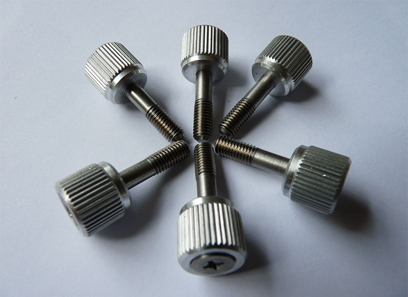
Straight Knurling
The straight pattern features a series of clean, parallel ridges that run perfectly parallel to the longitudinal axis of the part. This layout is ideal for components that require linear sliding adjustment or must press securely into a matching plastic housing. The straight ridges prevent rotational slippage while allowing relatively easy insertion along the axis of the assembly. You frequently see this clean styling on simple thumbscrews, electrical connectors, and the handles of precision laboratory equipment.
HelicalKnurling
Helical configurations feature helical ridges that slant either to the left or to the right at a specific predetermined angle. This angular layout offers a unique aesthetic appeal while providing directional resistance against specific mechanical forces. Manufacturers sometimes use these single-angle diagonal textures to guide the flow of plastics or adhesives during overmolding processes. This specific geometry ensures that the molded material locks tightly onto the metallic core without any risk of loosening.
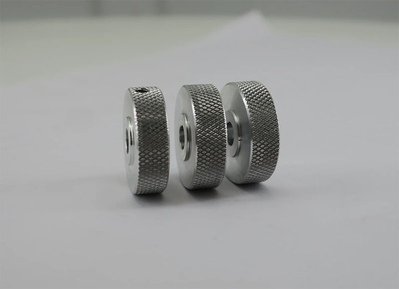
Diamond Knurling
The diamond pattern is undoubtedly the most recognizable and widely specified texture in the entire manufacturing industry. It combines right-handed and left-handed diagonal lines to create a beautiful matrix of small, diamond-shaped geometric projections.
A male diamond pattern features raised pyramidal points that dig slightly into the hand to provide maximum non-slip traction. This aggressive texture is perfect for heavy-duty industrial tools, gym equipment, and control valves that operators must turn with greasy hands. Conversely, a female diamond pattern consists of recessed pockets that offer a much smoother, less abrasive feel for delicate consumer electronics.
Understanding Pitch and Measurement Standards
To achieve the exact texture your application requires, you must accurately specify the pitch of the pattern on your blueprints. The pitch refers directly to the distance between the individual ridges or peaks on the textured surface of the part. Getting this measurement correct ensures the texture scales appropriately with the physical size of the product.
In the standard imperial measurement system, pitch is usually designated by Diametral Pitch (DP) or by Teeth Per Inch (TPI). A high TPI count, such as 96, creates an incredibly fine, velvety texture that feels smooth to the touch. A low TPI count, such as 16, yields a coarse, deeply grooved pattern designed for maximum physical grip.
In metric manufacturing environments, engineers measure pitch directly as the linear distance in millimeters from one ridge peak to the next. Common metric pitches typically range from a delicate 0.5 mm up to a very aggressive 2.0 mm profile. Designers must match the pitch to the overall diameter of the workpiece to maintain a clean, uniform look. If the circumference is not an exact multiple of the tool pitch, the pattern can track incorrectly and ruin the finish.
Material Selection Considerations for Best Results
Not all industrial metals behave the same way under the intense pressure or cutting action of texturing tools. Material selection plays a massive role in determining the ultimate sharpness, durability, and visual cleanliness of the finished pattern.
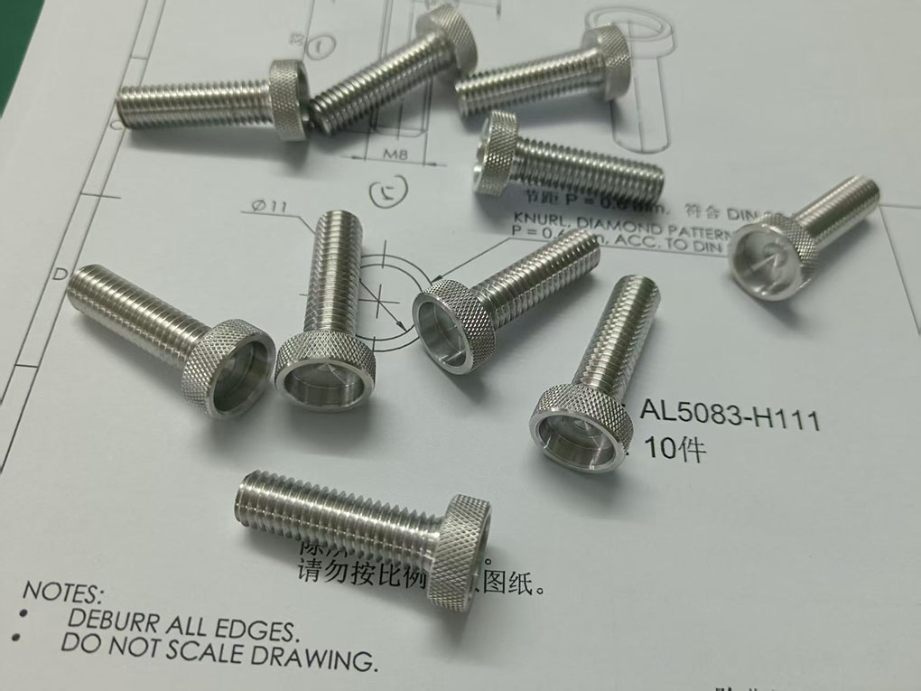
- Aluminum Alloys: Aluminum is a fantastic candidate for texturing because it is highly malleable and deforms easily under forming wheels. Grade 6061 aluminum accepts beautiful, crisp patterns while remaining incredibly lightweight and naturally resistant to atmospheric corrosion.
- Brass and Copper: These softer yellow metals are highly responsive to both forming and cutting operations. Brass textures look exceptionally premium and are widely utilized in high-end musical instruments, custom cabinetry hardware, and electrical components.
- Carbon and Alloy Steels: Medium carbon steels respond beautifully to texturing, but they require significantly higher forming pressures than softer metals. The resulting textured teeth are remarkably tough, wear-resistant, and capable of enduring years of brutal industrial abuse.
- Stainless Steel: This exceptionally hard material work-hardens rapidly under pressure, making traditional forming operations quite challenging. Machine operators must use robust cutting tools, heavy sulfurized cutting oils, and slower rotational speeds to prevent premature tool failure.
- Plastics and Polymers: Certain rigid plastics like Delrin or ABS can accept molded or directly machined textures quite successfully. However, engineers must carefully manage tool temperatures to prevent the plastic material from melting or smearing during the process.
Best Practices for Product Designers and Engineers
Designing a part for successful texturing requires a deep understanding of how tools interact with the raw metal surface. If you follow a few foundational manufacturing guidelines, you can drastically reduce production costs and eliminate costly component failures.
First, you must always specify whether you require a cutting or a forming methodology directly on your engineering drawings. This clarity allows the machine shop to select the proper tooling and program the CNC lathe cycles correctly. Second, you should always provide a small relief groove at the beginning and end of the textured zone. This crucial groove gives the wide texturing wheels a clean area to exit, preventing ugly, distorted edges.
Furthermore, you must account for the inevitable outer diameter expansion if you choose the traditional pressure forming method. The material displaced from the grooves moves outward, increasing the final diameter of the part past its original dimensions.
If your assembly requires strict tolerances, you must calculate this expansion precisely before turning the initial blank down. Finally, avoid specifying deep patterns on thin-walled parts, as the high forces can easily crush or warp the internal geometry.
Elevate Your Manufacturing Quality with SYM Machining
Achieving a flawless, highly uniform textured finish requires state-of-the-art machinery, precision tooling, and extensive technical expertise. Minor programming errors or incorrect material calculations can quickly result in misaligned patterns, ruined workpieces, and costly production delays. When your product line demands exceptional ergonomics and pristine cosmetic finishes, partnering with a proven manufacturing expert is absolutely essential.
SYM Machining specializes in delivering premier precision turning, CNC milling, and advanced surface textures for a diverse range of demanding industries. Our highly experienced engineering team understands the intricate nuances of both pressure forming and high-speed cut texturing methodologies. We work closely with your design team to select the ideal patterns, pitches, and materials for your unique application.
We utilize advanced CNC technology to guarantee perfect geometric tracking, pristine edge transitions, and absolute batch-to-batch consistency every single time. Do not compromise on the tactile feel, user safety, or visual appeal of your critical components. Contact SYM Machining today to discuss your next project, request a detailed quote, and elevate your manufacturing quality.
Related articles: