In modern manufacturing, precision isn’t just an advantage—it’s a necessity. When tolerances reach extreme levels, such as ±0.001mm (1 micron), only a select few industries, materials, and advanced machining technologies can meet the demand. This guide explores ultra-tight tolerance machining, including: Key industries, Best materials ,Achievable dimensions, High-precision machining processes. Discover how cutting-edge manufacturing achieves near-perfect accuracy and where it’s applied in aerospace, medical, optics, and more.
What Is Ultra-Tight Tolerance Machining?
Tolerance in machining defines how much a specific dimension is allowed to vary. A ±0.001mm tolerance means the component must be manufactured within 1 micron—1/1000th of a millimeter—above or below the nominal dimension.
Such tolerances are significantly tighter than the usual industry standards:
- General CNC machining: ±0.1mm
- Precision CNC machining: ±0.01mm
- Ultra-precision: ±0.001mm or tighter
This level of precision is typically found in high-performance systems where even microscopic deviations can lead to performance loss, safety risks, or system failure.
Industries That Demand Ultra-Tight Tolerance Machining
Not every application requires such stringent tolerances. Ultra-tight tolerance machining is usually reserved for mission-critical components where precision is non-negotiable.
Precision Mold Manufacturing
- High-performance molds for semiconductors, optics, and medical injection molding require flawless geometry.
- Insert fit, cavity detail, and surface finish must be tightly controlled to prevent flashing or warping during molding.
Medical Device Manufacturing
- Surgical implants, stents, and diagnostic devices need micron-level accuracy to integrate seamlessly with human anatomy and function.
- Aerospace Components, Jet engine parts, satellite mechanisms, and optical systems in space exploration demand dimensional stability across extreme conditions.
Watchmaking and Micro-Mechanics
- Microscopic gears and axles in luxury timepieces require ultra-precision for long-lasting, smooth movement.
Metrology Equipment and Gauges
- Devices that measure other components need to be more precise than the parts they inspect.
Dimensions That Can Achieve Micron-Level Precision
Not All Features Require ±0.001mm,when designing precision parts, it’s a mistake to assume that all dimensions should be held to the tightest possible tolerance. In reality, ultra-tight tolerances like ±0.001mm are only necessary for specific, function-critical features. Over-tolerancing can dramatically increase cost, slow production, and introduce unnecessary risk without improving performance.
Precision Is About Purpose, Not Perfection
Ultra-precision should be strategically applied to dimensions that directly impact:
- Fit between parts
- Functional alignment
- Mechanical movement
- Sealing or optical accuracy
Tolerance design should always reflect the real-world function of the feature—not an arbitrary pursuit of perfection.
Common Features That Require Ultra-Tight Tolerances
| Feature Type | Why Precision Matters | Common Tolerances |
| Shafts and bores | Ensure interference or sliding fit | ±0.001mm to ±0.003mm |
| Locating holes/pins | Accurate part alignment during assembly | ±0.001mm true position |
| Mating surfaces | Prevent air or fluid leaks | Flatness < 0.002mm |
| Precision cavities | Critical for molding or optical quality | ±0.001mm on geometry |
| Optical mounts | Maintain focus and clarity | Angular ±0.01° |
| Step depths or ledges | Component seating or sealing | ±0.002mm on depth |
These features typically appear in precision molds, metrology tools, aerospace assemblies, medical devices, and optical systems.
Features That Rarely Need Ultra-Tight Tolerances
Many non-critical features can be machined to general tolerances (±0.05mm or looser) without impacting functionality:
- External dimensions that don’t interface directly with other parts
- Surfaces that are only cosmetic or structural
- Clearance holes or light-duty mounting brackets
- Deep cavity depths with no functional constraint
- Non-contact faces in housings or support frames
Real-World Example: Tolerance Differentiation in a Mold Insert
| Feature | Purpose | Typical Tolerance |
| Guide pin hole | Critical alignment | ±0.001mm (H7 fit) |
| Parting line surface | Flash-free seal | Flatness < 0.002mm |
| Cooling channel port | Loose fit for tubing | ±0.1mm |
| Insert perimeter | Drop-in fit into mold base | ±0.01mm |
| Label recess | Cosmetic only | ±0.05mm |
This selective approach helps optimize cost, maintain function, and reduce machining complexity.
The Risk of Over-Designing Tolerances
Applying tight tolerances universally leads to serious downsides:
- Increased cost due to slow feeds, fine tools, and extra inspection
- Higher rejection rates from minor variation
- Extended lead times for rework and secondary finishing
- Tool wear and scrap increases drastically
Best Practices for Precision Tolerance Design
- Use GD&T to clearly define form, orientation, and position when functionally required.
- Focus on assembly interfaces—tolerances should ensure parts align, fit, and seal correctly.
- Consult with your machining partner to determine process capabilities before finalizing tolerances.
- Avoid stacking tight tolerances unless absolutely necessary.
- Communicate tolerance zones on technical drawings with clarity.
Final Thought: Design for Function, Manufacture for Efficiency
Ultra-precision is a targeted tool, not a universal standard. Only specific dimensions tied to function or mating relationships should carry the burden of ±0.001mm tolerances. A well-engineered part uses precision only where it impacts performance, allowing manufacturers like SYM Precision Machining to deliver high-accuracy components efficiently and cost-effectively.
Tips for Designing Precision Features Wisely
- Use GD&T (Geometric Dimensioning & Tolerancing) to define only critical form/position constraints.
- Communicate the function of each feature to your machinist—context helps prioritize.
- Avoid blanket tolerances on drawings; use general tolerances for non-critical dimensions.
- Collaborate with manufacturing engineers early to align expectations and process capabilities.
Why Selective Tolerance Design Matters?
| Area | Without Precision Design | With Selective Tolerance |
| Cost | High tooling and scrap | Lower production cost |
| Lead Time | Long (multiple reworks) | Optimized |
| Quality | High rejection rate | Stable, consistent output |
| Assembly | Overly rigid or complex | Efficient and functional |
Result: Smart tolerance allocation balances function, manufacturability, and cost.
Metals vs. Plastics: Which Are Better for High Precision?
When it comes to ultra-tight tolerances like ±0.001mm, metals are almost always the preferred choice. Plastics, while useful in many industries, come with significant limitations that make them unsuitable for ultra-precision machining.
Best Materials for Ultra-Precision Machining
| Material | Key Benefits | Applications |
| Tool Steels (D2, H13, S7) | Hard, stable, wear-resistant | Precision molds, dies |
| Stainless Steel (303, 316) | Corrosion-resistant, tough | Medical implants, surgical tools |
| Titanium | Lightweight, biocompatible | Aerospace, medical |
| Carbide | Extremely hard, wear-resistant | Cutting tools, gauges |
| Aluminum (7075, 6061) | Lightweight, good machinability | Aerospace housings |
Why Plastic Machined Parts Struggle with ±0.001mm Tolerances?
While high-performance plastics such as POM (Delrin), PEEK, and PTFE are often machined for precision components, they rarely meet the ultra-tight standards of ±0.001mm due to several inherent material limitations:
| Issue | Result |
| High thermal expansion | Dimensional drift during machining or storage |
| Low rigidity | Deflection, vibration, inconsistent cuts |
| Moisture absorption | Size changes after machining |
| Poor surface finish | Limited finishing options, lower precision |
| Metrology issues | Difficult to measure reliably |
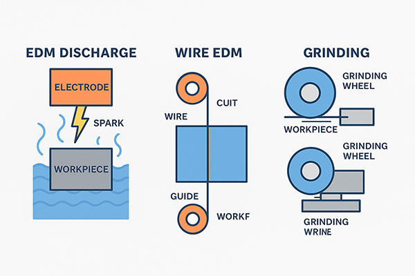
Ultra-Tight Tolerance Machining: Techniques & Machine Comparison
Achieving micron-level precision (±0.001mm or tighter) requires advanced machining techniques. Each method has unique strengths depending on material, geometry, and tolerance requirements. Below, we compare CNC turning, CNC milling, EDM (Electrical Discharge Machining), wire cutting, and grinding for tight-tolerance applications. Which Method is Best for Tight Tolerances?
| Process | Best Tolerance | Best For | Material Limitations |
| CNC Turning | ±0.002mm | Rotational parts | Limited geometries |
| CNC Milling | ±0.005mm | Complex 3D shapes | Slightly less precise |
| EDM | ±0.002mm | Hard metals, intricate details | Conductive only |
| Wire EDM | ±0.001mm | Precision 2D cuts | Conductive only |
| Grinding | ±0.0005mm | Ultra-fine finishes | Mostly metals |
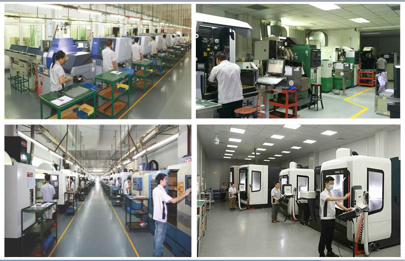
Each method has trade-offs in speed, cost, and material compatibility. Choosing the right process depends on part geometry, material, and required tolerances. At SYM Precision Machining, ultra-tight tolerances are made possible through non-traditional, high-accuracy processes, including Precision Grinding, EDM, and slow Wire Cutting.
SYM Precision Grinding (Surface, Cylindrical, and Jig Grinding)
Grinding is the gold standard for dimensional stability and ultra-smooth surfaces. SYM uses high-rigidity machines with fine-grit wheels and closed-loop control. Grinding tight outer and inner diameters achieve ±0.001mm or better on short features, flatness and parallelism < 1µm over small areas, surface finishes < Ra 0.2µm
SYM EDM Mirror Discharge (Fine EDM)
Also known as “mirror-finish EDM,” this specialized process removes material with extreme precision using electrical spark erosion—ideal for hardened tool steels. Accuracy±0.001mm dimensional tolerance, surface finish up to Ra 0.1µm (mirror grade). Typical Use for some mold inserts, medical or optical tooling, micro-cavities and tight radius corners.
SYM Slow Wire Cutting
Unlike traditional EDM, slow wire EDM uses fine brass or tungsten wire at controlled speeds to produce exceptionally precise cuts in hard materials. The precision Achieve ±0.001mm or better in wire-cut geometry, excellent straightness and squareness. Normally used for thin wall profiles, precision punches and dies.
Conclusion
Tight tolerance machining (+0.001mm) is at the heart of industries where precision matters. It requires a deep understanding of materials, machines, and environmental factors. While challenging and costly, the results are unmatched in reliability and performance. Choosing a partner like SYM Precision Machining means trusting your critical parts to experts who live and breathe precision.