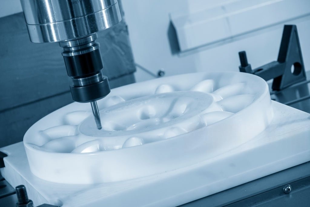
In high-end manufacturing, precision is not merely a specification; it is a promise. When engineering blueprints demand tolerances measured in microns, the margin for error completely vanishes. Yet, machinists and engineers frequently encounter a frustrating, shape-shifting adversary: structural deformation. A component can check out perfectly on a coordinate measuring machine while still clamped to the fixture, only to warp, twist, or bow the moment it is released.
Deformation in lavorazione di precisione is a deceptive challenge because it rarely stems from a single isolated mistake. Instead, it is the cumulative result of a complex interplay among material science, thermodynamics, mechanical forces, and systemic dynamics. When thin-walled aerospace structural members, intricate medical devices, or high-speed automotive components warp, production timelines stall and scrap rates soar. To achieve true dimensional stability, manufacturers must look beyond the cutting edge of the tool and understand the underlying physics that force metal and plastic to lose their shape.
1. The Internal Battle: Residual Stress and Material Behavior
Every piece of raw stock enters the machining bay carrying a hidden history. Whether a metal bar or plate has been forged, extruded, cold-rolled, or heat-treated, the manufacturing process leaves behind a complex web of internal energy known as residual stress. Under equilibrium conditions, these internal tension and compression forces balance each other out perfectly, allowing the material to maintain its external shape.
Why Machining Can Change the Shape of Your Metal Parts?
When a cutting tool first touches a workpiece, it breaks a delicate balance inside the material. As the machine removes outer layers of metal, it also strips away part of the material’s internal stress network. Suddenly, the remaining forces become uneven. To find a new balance, the workpiece may shift, bow, or twist.
This problem is most common in high-performance materials like aircraft-grade aluminum (such as 7075-T6) or titanium alloys. These metals go through intense hardening and strengthening processes, which lock in a lot of internal energy.
How Material Type Affects Stability?
The way a material reacts to machining depends on its natural properties. Metals with a high thermal expansion rate or a low elasticity modulus are more likely to change shape. This becomes a serious issue when large amounts of material are removed—for example, when machining aerospace parts from a solid block down to a lightweight frame of thin ribs. That massive removal of material releases a huge amount of stored energy.
If manufacturers don’t use proper stress-relieving methods or choose the right materials, the finished part simply won’t hold its intended shape.
2. Mechanical Forces: Clamping Pressure and Cutting Dynamics
While internal stresses lie dormant until awakened by material removal, external mechanical forces actively push, pull, and distort the workpiece throughout the cutting cycle. The first contributor to this issue is often the very mechanism designed to hold the part stationary: the workholding fixture.
How Clamping and Cutting Forces Distort Your Machined Parts
To stop a part from vibrating or moving during high-speed milling or turning, operators must clamp it tightly. But if the clamping force is applied across thin walls or unsupported areas, the workpiece will bend or compress while still in the fixture. This is called elastic deformation.
The cutting tool then machines flat surfaces and precise features into this temporarily distorted part. The problem appears when the clamps are released. As the material springs back to its natural shape, all those newly machined features instantly become misaligned, out of round, or no longer parallel.
The Hidden Damage from Cutting Forces
At the same time, the constant contact between the cutting tool and the workpiece creates intense local stress. As the tool cuts through the metal, it pushes, pulls, and twists the material. If the tool is dull, has the wrong shape, or runs at the wrong speed, it stops slicing cleanly. Instead, it begins plowing against the metal.
This plowing action creates a high-pressure zone just ahead of the cutting edge. It microscopically deforms the surface layer of the workpiece and leaves behind a fresh layer of surface stress. Over time, that hidden stress causes the part to warp—long after the machining is finished.
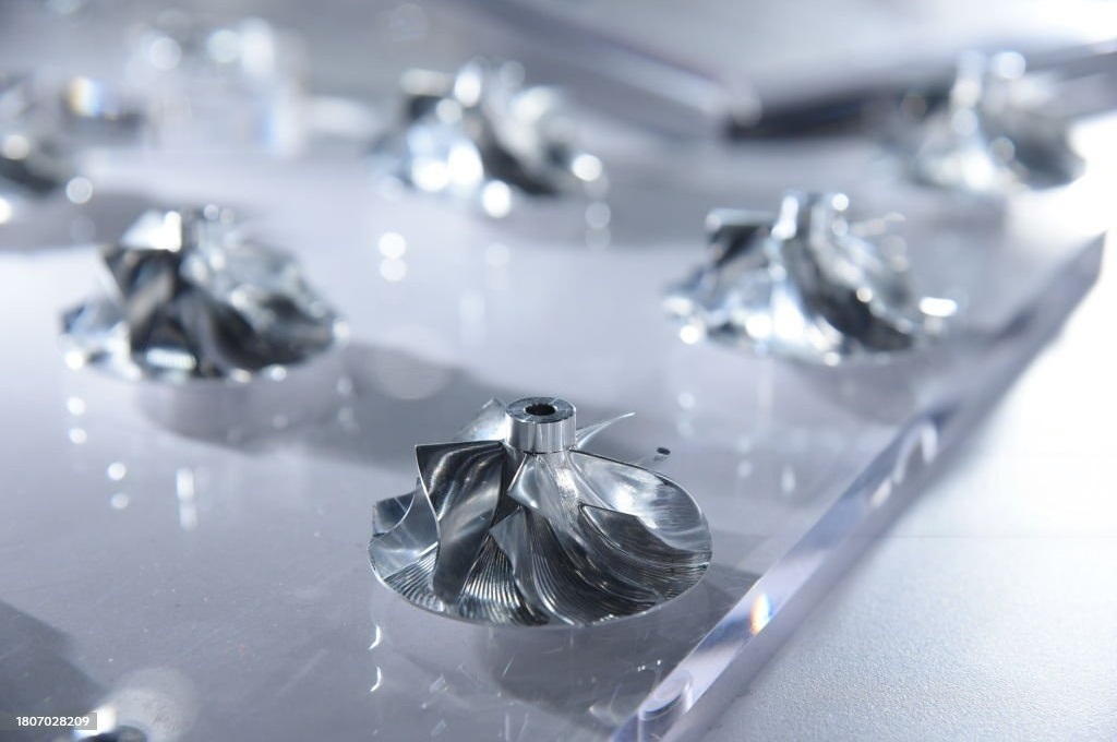
3. The Thermomechanical Crisis: Cutting Heat and Thermal Gradients
Precision machining is an energy-intensive process that converts mechanical work into heat. The vast majority of this thermal energy is intended to escape through the severed metal chips, but a critical percentage inevitably bleeds into the cutting tool and the workpiece itself.
How Heat and Cooling Mistakes Cause Warping in Metal Parts
When the outer surface of a metal part gets very hot but the core stays cool, a strong temperature difference forms. The hot surface wants to expand, but the cold, hard material underneath holds it back. This creates thermal stress—and at high temperatures where metals become softer, that stress can easily exceed the material’s strength.
Then, as the part cools down, the surface shrinks unevenly. The result is thermal distortion: warping, cupping, or parts that slowly drift out of their intended shape.
Why Bad Cooling Makes Things Worse
Poor cooling methods can turn this problem into a crisis. Flooding an overheated workpiece with cold, poorly aimed metalworking fluid causes thermal shock. Instead of cooling the part gently and evenly, this sudden quenching locks high thermal stress into the outer layers of the metal’s microscopic structure.
In ultra-precision machining, the stakes are even higher. Even a temperature change of just a few degrees inside the machining area can cause a cutting tool or a metal part to expand enough to ruin an entire production run.
4. Systemic Vulnerabilities: The Machine-Tool-Fixture Complex
Deformation cannot be analyzed by looking at the workpiece in isolation; it must be viewed as a failure of the entire process system. The machine tool, the spindle, the cutting tool, the holder, and the fixture form a continuous closed-loop structural circuit. Any weakness or lack of rigidity within this loop introduces vibration and deflection that directly degrades part geometry.
When the Machine Itself Causes Part Warping
Under heavy cutting loads, no machine tool is perfectly rigid. Every part of the machine—from the frame to the spindle—undergoes tiny elastic bends and deflections. If a machining center lacks enough static or dynamic stiffness, or if its spindle bearings have micro-play, the cutting tool will not follow its programmed path with total accuracy.
Instead, the machine flexes away from high-pressure cutting zones. This creates an uneven depth of cut, making the finished part look like it has warped—even when the material itself is fine.
Hidden Errors Built Into the Machine
Beyond flexibility, the machine’s own geometry can cause problems. Small construction errors—like the X and Y axes not being perfectly square, or ball screws growing slightly as the machine heats up over hours of operation—gradually transfer into the workpiece.
As a machine warms up during a shift, its structural columns can lean, and its spindle may extend forward. If the manufacturing system does not account for this thermal movement, the resulting size and shape errors are often blamed on part warping. In reality, the root cause lives inside the machine itself.
5. Multi-Dimensional Optimization Strategy
Overcoming deformation requires a shift from reactive troubleshooting to proactive, systematic engineering. Because distortion arises from multiple overlapping vectors, the solution must be equally comprehensive, spanning material conditioning, geometric design, advanced toolpath programming, and environmental isolation.
Material Conditioning and Design Sensibility
Defense starts before the spindle spins. Raw materials need special heat treatment first. This includes artificial aging or solution annealing. Cryogenic stress-relieving also helps reduce internal stress.
Engineers should avoid uneven shapes that cause warping. Place pockets and thin ribs symmetrically across the part.
Keep wall thickness the same throughout the component. This ensures the material expands and contracts evenly.
It prevents twisting and distortion during machining.
Advanced Toolpath Planning and Process Controls
Modern Computer-Aided Manufacturing (CAM) strategies offer powerful defense mechanisms against deformation. Traditional heavy slotting passes, which plow through metal and generate massive mechanical and thermal loads, are being replaced by dynamic, trochoidal milling toolpaths. By utilizing a small radial depth of cut paired with a deep axial cut, dynamic milling maintains a highly consistent chip load and drastically reduces cutting forces while channeling the vast majority of frictional heat directly into the escaping chips.
Additionally, multi-stage machining sequences are vital. Instead of roughing and finishing a single feature to completion before moving to the next, the entire component should be roughed out, allowed to rest and stabilize, and then finished using dedicated, low-force skim cuts. This allows the primary material stresses to release safely during the roughing phase, ensuring that the final finish passes are executed on a stable, relaxed workpiece.
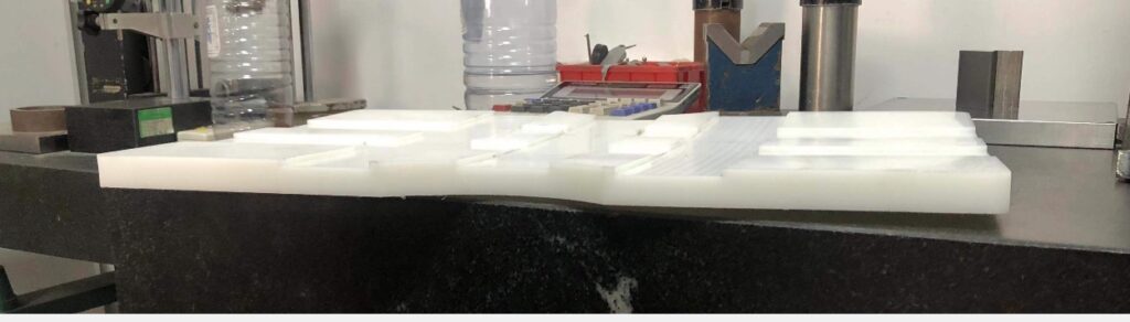
6. Systematic Process Control in High-End Manufacturing
In high-precision manufacturing, guesswork is not enough. Aerospace housings, optical parts, and semiconductor components demand perfection. Manual adjustments and operator intuition often fail. Real control requires smart, data-driven systems.
Predict Software Before You Cut
Advanced shops use simulation software first. It predicts cutting forces and heat before machining starts. Engineers can then find high-risk zones. These include thin walls that may bend, or areas where too much heat builds up.
Digital modeling helps optimize feed rates and spindle speeds. It also improves fixture placement—all in a virtual world. This ensures stable, reliable machining once real production begins.
Smart Systems That Adapt in Real Time
High-end production environments reduce distortion through systematic control. They use real-time thermal monitoring. Adaptive systems automatically adjust feed rates based on spindle deflection. Advanced workholding tools—like vacuum chucks or hydraulic fixtures—spread forces evenly.
These technologies protect the workpiece from harmful machining variables. The result is a highly repeatable process. Perfect parts are delivered consistently, run after run.
Secure Your Tolerances with SYM Machining
Managing structural deformation is the dividing line between basic manufacturing and true precision engineering. It requires deep metallurgical insight, elite process control, and an uncompromising commitment to structural stability. When your designs demand flawless execution without structural compromises, you need a manufacturing partner that understands the physics of precision.
Bring your most challenging, high-tolerance projects to Lavorazione SYM. Our expert engineering team specializes in advanced stress-mitigation strategies, optimized toolpath planning, and ultra-precise manufacturing setups tailored to defeat deformation before it starts.
Articolo correlato:
I 6 fatti più importanti da sapere sui pezzi di tornitura CNC per l'ingegneria di precisione
Consigli degli esperti per la progettazione di parti di tornitura di precisione