Learn everything about PEEK plastic CNC machining — from material advantages, machining process, applications, tooling, to expert tips for flawless results.
Introduction to PEEK Plastic CNC Machining
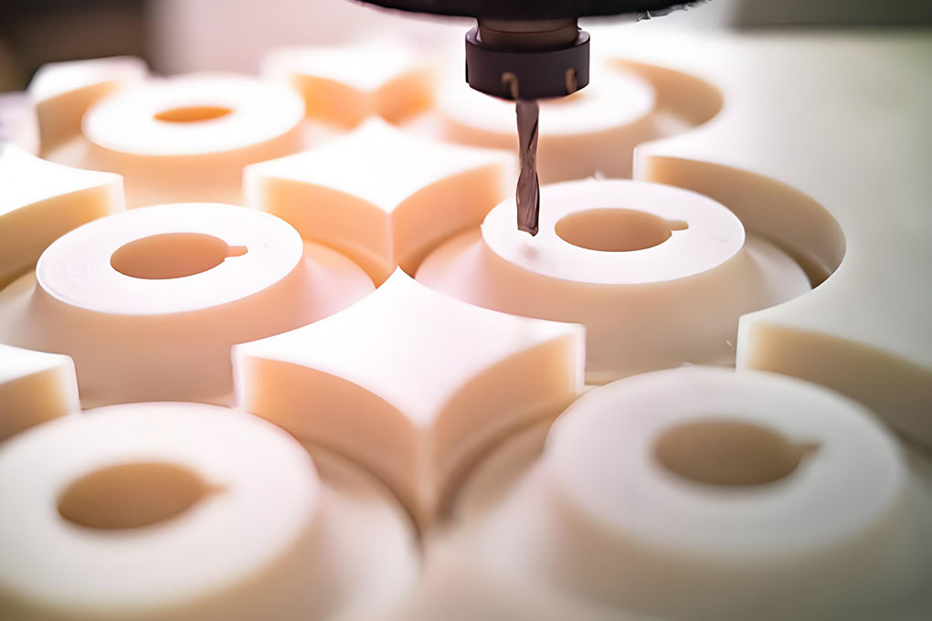
PEEK plastic CNC machining represents the intersection of material science and modern engineering. This process unlocks the full potential of one of the world’s most advanced thermoplastics, offering unmatched strength, chemical resistance, and heat performance. When done right, it results in components that meet the highest standards of precision and reliability.
Polyetheretherketone, or PEEK, is a high-performance plastic used in precision engineering. When combined with CNC (Computer Numerical Control) machining, it becomes a powerful solution for industries that need durable, heat-resistant, and precise components. From aerospace to medical implants, PEEK plastic CNC machining is transforming how we design and manufacture advanced plastic parts.
This article explores the full process of working with PEEK through CNC machining. Whether you are an engineer, product designer, or manufacturer, understanding how PEEK behaves during machining can lead to better product performance and longer-lasting components.
Types of PEEK Material and Their Properties
PEEK stands for Polyetheretherketone. It is a semi-crystalline thermoplastic polymer known for its high heat resistance, mechanical strength, and chemical stability. It is available in several grades and formulations to meet specific application needs. These variants differ in terms of filler materials, thermal stability, wear resistance, and strength. Its biocompatibility and strength-to-weight ratio make it an ideal replacement for metal in high-tech applications.
Below is a comprehensive explanation of the major types of PEEK and their respective material properties.
1. Unfilled (Virgin) PEEK
This is the purest form of PEEK (PEEK 450G, PEEK 150G). It contains no fillers or additives, making it ideal for applications requiring biocompatibility, chemical purity, or high flexibility.
Typical Applications:
- Medical implants and surgical tools
- Semiconductor parts
- Food contact components
Properties:
| Property | Value |
| Density | ~1.30 g/cm³ |
| Tensile Strength | 90–100 MPa |
| Elongation at Break | 20–50% |
| Flexural Modulus | ~4 GPa |
| Melting Point | 343°C |
| Glass Transition Temp (Tg) | 143°C |
| Continuous Use Temp | ~260°C |
| Dielectric Strength | 17–20 kV/mm |
2. Glass-Filled PEEK (GF30 /GF20 PEEK)
Glass fiber is added (typically 30% by weight) to improve stiffness and dimensional stability. (450GL30, 150GL20) This makes it suitable for structural applications that need less deformation under load.
Typical Applications:
- Structural supports
- Pump housings
- Load-bearing components
Properties:
| Property | Value |
| Density | ~1.51 g/cm³ |
| Tensile Strength | ~120 MPa |
| Flexural Modulus | ~9 GPa |
| Elongation at Break | 2–3% |
| Thermal Conductivity | Higher than unfilled PEEK |
| Heat Deflection Temp (1.8 MPa) | ~315°C |
Key Benefit: Higher rigidity, better load handling, Consideration: Reduced ductility and increased brittleness compared to virgin PEEK.
3. Carbon-Filled PEEK (CF30/CF20 PEEK)
Carbon fiber is added (30% by weight) to enhance stiffness, thermal conductivity, and wear resistance. (450CA30, 150CA20 CF PEEK) also has lower expansion, making it ideal for precision components.
Typical Applications:
- Bearings and bushings
- Aerospace fasteners
- High-speed moving parts
Properties:
| Property | Value |
| Density | ~1.41 g/cm³ |
| Tensile Strength | ~140 MPa |
| Flexural Modulus | ~12 GPa |
| Coefficient of Thermal Expansion | Lower than GF PEEK |
| Wear Resistance | Excellent |
| Electrical Conductivity | Slightly conductive |
Key Benefit: Best for high-wear, high-load applications., Consideration: Not electrically insulating like other grades.
4. Bearing Grade PEEK (PEEK HPV)
This is a specialty grade with PTFE (Teflon), graphite, and carbon fiber fillers. And other special PEEK, such as PVX100, PEEK HT, high temperature stage. PEEK ESD,It offers low friction, excellent wear, and self-lubrication.
Typical Applications:
- Gears
- Seals
- Sliding surfaces
- Compressors
Properties:
| Property | Value |
| Density | ~1.45 g/cm³ |
| Coefficient of Friction | 0.1–0.2 |
| Wear Factor | Low |
| PV Limit | Very High |
| Thermal Stability | ~250–300°C continuous use |
Key Benefit: Great for non-lubricated, high-speed motion. Consideration: Slightly reduced mechanical strength.
5. Medical-Grade PEEK (PEEK-OPTIMA™, Zeniva®)
Certified for implantable and non-implantable medical devices, this grade is highly pure, sterilizable, and FDA/ISO compliant.
Typical Applications:
- Spinal cages
- Orthopedic implants
- Surgical instruments
Properties:
| Property | Value |
| Biocompatibility | ISO 10993 / USP Class VI |
| Sterilization Methods | Steam, Gamma, EtO |
| Tensile Strength | ~95–100 MPa |
| Elongation at Break | 20–30% |
| Radiolucency | Yes (in X-ray imaging) |
Key Benefit: Safe for long-term body contact. Consideration: Expensive due to cleanroom manufacturing.
Summary Table: Comparison of Major PEEK Grades
| Property | Virgin PEEK | Glass-Filled PEEK | Carbon-Filled PEEK | Bearing Grade PEEK | Medical-Grade PEEK |
| Density (g/cm³) | ~1.30 | ~1.51 | ~1.41 | ~1.45 | ~1.30 |
| Tensile Strength (MPa) | 90–100 | ~120 | ~140 | ~100 | 95–100 |
| Flexural Modulus (GPa) | ~4 | ~9 | ~12 | ~5–6 | ~4 |
| Elongation at Break (%) | 20–50 | 2–3 | 1.5–2.5 | 3–5 | 20–30 |
| Wear Resistance | Moderate | Moderate | High | Very High | Moderate |
| Biocompatibility | Yes | No | No | No | Yes |
| Cost per kg (USD) | $400–600 | $600–800 | $700–900 | $800–1000 | $1000–1500+ |
Part Design Tips for CNC Machined PEEK Components
Well-designed parts lead to better machinability and performance. Here are some guidelines:
1. Wall Thickness
• Keep thin walls >1.5 mm if possible
• Avoid extremely thin ribs unless necessary
2. Corner Radii
• Use internal radii >0.5 mm to reduce stress
• Sharp corners increase fracture risk
3. Threads and Taps
• Use helicoils or inserts for load-bearing threaded holes
• Consider milled threads for improved accuracy
4. Undercuts and Complex Geometry
• Use 5-axis machining for curved channels
• Consider split designs for parts that are hard to fixture
Tips for Application-Specific Design Success
- Minimize Sharp Corners: Use fillets to reduce internal stress and tool wear, especially in implant or structural applications.
- Account for Thermal Expansion: In aerospace and automotive designs, allow clearance for PEEK’s thermal expansion (≈47×10⁻⁶/°C).
- Material Certification: For medical and food applications, ensure materials meet USP Class VI or FDA compliance.
- Consider Fillers: Glass or carbon-fiber-filled PEEK offers higher stiffness and wear resistance—ideal for structural parts or bearing surfaces.
- Use Dry Machining: For parts needing biocompatibility (like implants), avoid coolants and opt for dry cutting to reduce contamination.
- Add Undercuts for Locking Mechanisms: In electronic or medical components, undercuts can help parts lock securely without extra hardware.
- Plan for Sterilization Tolerance: Medical devices should be designed to endure repeated autoclaving without dimensional drift.
- Match Finish to Application: Semiconductor parts may need ultra-smooth finishes to prevent particle generation, while automotive parts can tolerate rougher surfaces.
- Design for Tool Access: In high-precision industries, ensure cavities are accessible by small-diameter tools without excessive tool deflection.
- Post-Processing Options: Consider annealing or polishing if parts will face mechanical stress or tight visual inspection.
Application-Specific Design Guideline for PEEK Machining
| Industry | Key Application Examples | Design Focus | Tolerances | Surface Finish | Material Recommendation |
| Aerospace | Lightweight brackets, thermal insulation | Weight reduction, high temp resistance, vibration damping | ±0.02 mm or tighter | Ra 0.8–1.6 μm (may require polishing) | Carbon-Filled PEEK, Glass-Filled PEEK |
| Medical Implants | Spinal cages, cranial plates | Biocompatibility, X-ray transparency, fatigue resistance | ±0.01–0.03 mm | Ra 0.4–0.8 μm (mirror polish if required) | PEEK-OPTIMA™, Invibio® Implant-Grade PEEK |
| Medical Devices | Surgical tools, endoscopic components | Sterilization resistance, mechanical strength | ±0.05 mm | Ra 0.8–1.2 μm | Victrex® HT, Unfilled PEEK |
| Semiconductors | Wafer clamps, test sockets | High purity, low particle generation, anti-static | ±0.01 mm | Ra 0.4–0.6 μm (ultra-smooth) | Unfilled PEEK, PEEK-CF30 |
| Automotive/EV | Gears, connectors, housings | Wear resistance, light weight, thermal stability | ±0.03–0.05 mm | Ra 1.0–1.6 μm (lubricated possible) | Bearing Grade PEEK, PEEK-GF30 |
| Oil & Gas | Seals, valve seats, sensor enclosures | Chemical resistance, pressure resistance, long service life | ±0.03 mm | Ra 0.8–1.2 μm | HPV PEEK, Carbon-Filled PEEK |
| Food Processing | Pump parts, seals, guides | Food safety, resistance to sterilization and abrasion | ±0.05 mm | Ra 0.8–1.6 μm (food-grade finish) | FDA-Approved Unfilled PEEK |
| Electrical/Connectors | Terminal insulators, housings | Electrical insulation, dimensional accuracy, high temperature stability | ±0.02–0.05 mm | Ra 0.8–1.2 μm | Glass-Filled PEEK, Conductive PEEK |
| 3D Printing | Jigs, functional prototypes | High strength at elevated temperature, ease of printing | ±0.1 mm (dependent on print type) | Ra 3.0+ μm (may need post-machining) | Amorphous PEEK, PEEK Filament |
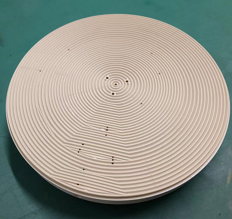
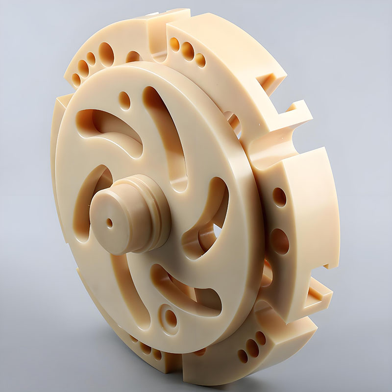
PEEK Machining case study
PEEK is notoriously tough to machine, but with the right knowledge, setup, and tools, it can deliver world-class performance in applications where failure is not an option. Whether you’re working on a satellite part or a spinal implant, understanding the nuances of PEEK machining helps ensure long-term success and product integrity.
A normal check list of PEEK machining at SYM:
Material Preparation
- Confirm PEEK Grade: Unfilled, GF30, CF30, bearing-grade, or medical-grade?
- Check for Stress: Material must be annealed before precision machining.
- Annealing (if needed): Follow OEM-recommended thermal cycle.
- Clean Surface: Remove contaminants like oil, dust, or fingerprints.
Tooling Setup
- Select Tool Type:Carbide, diamond-coated, or PCD depending on grade.
- Choose Tool Geometry: Sharp edges, positive rake, 2–3 flutes for chips.
- Check Tool Condition: No dull edges, chips, or discoloration.
- Install Correct Holder: Use precision ER collets or shrink-fit holders.
- Calibrate Runout: Keep spindle runout <0.01 mm for tight tolerances.
Machine Setup
- Machine Type: 3-, 4-, or 5-axis CNC depending on part geometry.
- Workholding Method: Soft jaws, vacuum fixture, or custom jigs.
- Clamp Force Check: Avoid deformation of PEEK by excessive pressure.
- Zero Setup: Probe and set origin accurately using 3D touch probe.
- Thermal Stabilization: Run spindle warm-up cycle to reduce thermal drift.
Machining Parameters
- Cutting Speed: 250–800 m/min (grade-dependent).
- Feed Rate: 0.05–0.2 mm/tooth.
- Depth of Cut: 0.5–2.5 mm.
- Spindle Speed: Adjust based on tool diameter.
- Peck Drilling (if needed): Required for holes >3× diameter.
- Toolpath Strategy: Use climb milling and trochoidal strategies for better finish.
Cooling and Chip Management
- Choose Coolant Type: Air blast or mist preferred; water-soluble coolant if necessary.
- Set Air Pressure: High-speed air (50–100 PSI) for chip clearing.
- Avoid Flood Coolant: Not typically needed; may cause swelling in some cases.
- Chip Evacuation Check: Use vacuum or air assist to prevent chip re-cutting.
- Chip Collector Ready: Ensure chips are not contaminating machine enclosure.
Post-Machining & Inspection
- Deburring: Use ultrasonic bath or soft brushes.
- Surface Finish Check: Measure Ra (target: 0.8–1.6 µm).
- Dimensional Inspection: Use CMM or optical comparator for ±0.01 mm parts.
- Visual Inspection: Check for discoloration, burns, delamination.
- Cleaning: Ultrasonic or isopropyl alcohol bath (esp. medical parts).
Packaging & Handling
- Anti-static Packaging: For electronic or cleanroom parts.
- Dust-Free Environment: Pack in clean area or under laminar hood.
- Label with Material Grade: Especially critical for regulatory use.
- Store Flat: Avoid deformation in thin-walled parts.
Documentation
- Record Machining Parameters: For repeatability and process optimization.
- Save Tool Wear Data: Track tool life per batch.
- Maintain Lot Traceability: For medical/aerospace parts.
- QC Report Generated: Include dimensions, material certs, finish, and pass/fail.
Choosing an experienced supplier ensures strong, lightweight parts that pass inspection every time—and that’s something worth investing in. SYM Precision Machining delivers trusted, certified, and fast services for prototypes and production parts.
Conclusion
PEEK plastic CNC machining is a highly specialized field that enables the creation of strong, lightweight, and heat-resistant components. From medical implants to aerospace connectors, the applications are as diverse as they are demanding. With the right tools, settings, and understanding of the material’s behavior, PEEK can outperform metals and many other polymers in critical use cases.
Related articles