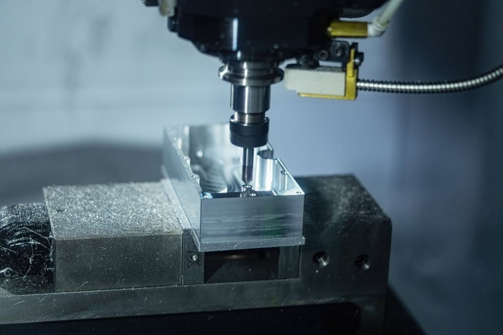
Achieving precise, uniform wall thickness in custom CNC milling stands as one of the most demanding challenges in precision manufacturing. When thin walls deflect under cutting pressure, the resulting dimensional inaccuracies compromise part functionality, structural integrity, and aesthetic quality. Engineers and machinists must balance cutting forces, material properties, and tooling strategies to maintain strict geometric tolerances across thin features. This comprehensive guide details the key factors, advanced techniques, and practical methodologies required to achieve perfectly consistent wall thickness in thin-walled CNC milled components.
Understanding the Physics of Wall Deflection
Thin walls in milled parts present a unique structural challenge because they lack structural rigidity during the machining process. As the cutting tool engages the material, mechanical force transfers directly into the wall feature. If the wall is unsupported, it flexes away from the cutting edge under radial cutting forces.
When a wall bends during a pass, the tool removes less material than intended. As the tool moves past, the deflected metal spring backs to its original position. This physical spring-back causes wall thickness variations, unwanted taper, and severe dimensional errors.
In severe cases, wall deflection induces chattering, which destroys surface finishes and accelerates tool wear. Machine operators must understand that wall rigidity decreases exponentially as the aspect ratio between wall height and thickness increases. A tall, thin wall behaves like a cantilever beam subjected to a point load. Controlling cutting forces becomes paramount when managing high-height-to-width aspect ratios in thin-wall features.
Furthermore, thermal expansion poses a secondary physical challenge during heavy cutting operations. Frictional heat builds up quickly in thin sections because the reduced material volume cannot dissipate thermal energy effectively. Thermal expansion pushes the wall into the cutter path, creating localized thin spots or unexpected gouges.
Material Selection and Internal Stress Dynamics
Material choice directly influences how a part reacts to machining forces and heat generation. Metals like aluminum 6061-T6 and titanium 6C-4V exhibit different elastic moduli, thermal conductivities, and internal stress states. Selecting the appropriate alloy setting is the foundational step in ensuring dimensional stability.
Residual stress within raw stock material presents a hidden threat to consistent wall thickness. Internal stresses originate during raw material manufacturing processes like rolling, forging, or extrusion. As machining removes exterior layers of metal, internal stress equilibrium shifts dramatically within the remaining structure.
Unbalanced residual stresses cause thin walls to warp, twist, or bow after unclamping from the fixture. Machinists must select stress-relieved material stock, such as T651 temper aluminum, to minimize post-machining movement. Thermal stress-relief heat treatments prior to final finishing passes also stabilize delicate geometric features significantly.
| Material Alloy | Elastic Modulus (GPa) | Thermal Conductivity (W/mK) | Machinability & Deformation Risk |
| Aluminum 6061-T6 | 68.9 | 167 | High machinability; moderate deflection risk due to lower stiffness. |
| Aluminum 7075-T6 | 71 | 130 | Superior strength; lower warping risk compared to 6061. |
| Stainless Steel 304 | 193 | 16.2 | High stiffness; high heat generation increases thermal deformation risk. |
| Titanium Grade 5 | 114 | 6.7 | High strength-to-weight ratio; poor thermal dissipation requires slow cuts. |
Tooling Selection and Geometry Optimization
Selecting the correct end mill geometry is critical to reducing radial forces on fragile wall structures. Standard end mills often exert excess lateral pressure, forcing thin sections to flex outward during execution. Machinists must select cutting tools specifically engineered to minimize radial deflective forces.
Helix angles play a decisive role in directing cutting forces during tool engagement. Standard 30-degree helix end mills generate significant radial force vectors that push against the wall surface. Switching to high-helix end mills, such as 45-degree or 50-degree variants, shifts cutting forces upward along the Z-axis. Upward axial forces pull the cutter along the wall rather than pushing horizontally against it.
Tool length-to-diameter ratio also impacts cutting stability and tool deflection directly. A long, slender end mill flexes under load, compounding the deflection of the wall itself. Engineers should choose the shortest possible cutting tool with the largest core diameter that fits the part geometry.
Tool coatings and rake angles further optimize the cutting environment for thin walls. Sharp, polished cutting edges with positive rake angles sheer material cleanly, reducing friction and force requirements. Advanced coatings like Titanium Aluminum Nitride lower friction coefficient, preventing material adhesion and localized thermal buildup.
Advanced Tool Path Strategies and CAM Programming
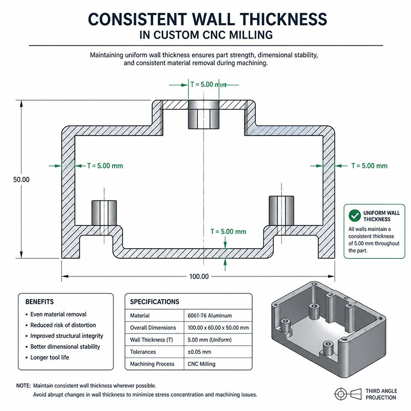
Modern Computer-Aided Manufacturing software provides powerful tool path strategies designed specifically to preserve wall rigidity. Conventional roughing passes that plunge directly adjacent to thin walls often induce catastrophic structural failure. Dynamic roughing and adaptive clearing strategies maintain consistent tool engagement angles, preventing force spikes.
Step-down strategies must prioritize structural support throughout the entire machining sequence. Machinists often apply a high-feed, shallow depth-of-cut approach to minimize lateral forces on delicate walls. Removing material in small Z-axis increments keeps lateral loads within acceptable structural limits.
Opposed cutting strategies provide an effective method for maintaining uniform thickness on isolated vertical walls. Machinists rough out both sides of the wall simultaneously using paired cutters, or alternate passes between sides in shallow steps. Leaving supporting material on the opposite side prevents the wall from flexing away from the active tool.
Optimizing finishing passes requires precise control over chip load and cutter engagement. Light finishing passes remove residual spring-back material left behind by roughing operations. Using climb milling during finishing passes produces cleaner surfaces and directs cutting forces into the solid base material rather than the unsupported wall edge.
Workholding, Fixturing, and Workpiece Support
Improper clamping is a frequent cause of wall distortion and non-uniform thickness in precision CNC milling. Over-tightening vice jaws distorts raw stock before machining even begins. When the jaws release after cutting, the part springs back, leaving curved or uneven wall geometry.
Soft jaws machined to match the exact profile of the part distribute clamping force evenly across large surface areas. Custom vacuum fixtures provide exceptionally uniform hold-down force for thin-bottomed parts without introducing mechanical stress. For thin vertical features, specialized dampening clamps prevent chatter and vibration without crushing delicate walls.
Support structures offer additional mechanical reinforcement during heavy cutting sequences. Temporary support ribs can be left in the CAD model and removed during final operations. These temporary features maintain structural rigidity while surrounding pockets are hollowed out.
Custom fill materials provide innovative support options for extremely delicate or complex wall profiles. Machinists can fill hollow cavities with low-melting-point alloys or specialized water-soluble wax. The solid filler material supports thin walls against cutting forces and absorbs harmful vibrations during machining passes. After machining concludes, heating or dissolving the filler leaves intact, highly accurate thin-walled structures.
Speeds, Feeds, and Cutting Parameter Optimization
Fine-tuning cutting parameters balances material removal rates with structural stability. High cutting speeds paired with reduced feed rates lower chip loads and minimize mechanical stress on thin features. Finding the optimal parameter window requires a deep understanding of chip formation physics.
High-Speed Machining techniques offer substantial advantages when milling thin-walled components. Operating at elevated spindle speeds reduces radial cutting forces while maintaining acceptable material removal rates. High-speed passes also carry heat away within the flying chips rather than transferring thermal energy into the workpiece wall.
Managing feed rates during corner transitions prevents severe force spikes and chatter. As an end mill enters an inside corner, tool engagement increases dramatically, causing tool deflection and localized wall thinning. CAM programmers must implement automatic feed rate reduction or trochoidal tool paths in corners to maintain uniform cutting forces.
Coolant delivery strategy is equally vital for heat management and chip evacuation. High-pressure coolant flushes recut chips out of deep cavities, preventing tool packing and sudden force spikes. Continuous, directed coolant flow stabilizes workpiece temperature, eliminating thermal expansion errors across long thin wall features.
Quality Control, Inspection, and Measurement Techniques
Verifying wall thickness accuracy requires non-destructive testing tools capable of measuring thin features precisely. Traditional mechanical calipers and micrometers often exert enough pressure to flex delicate walls, yielding inaccurate measurements. Quality control departments must utilize specialized, low-force, or optical measurement systems.
Ultrasonic thickness gauges deliver highly accurate wall measurements without requiring access to both sides of a wall feature. The device sends high-frequency sound waves through the material and calculates thickness based on echo timing. Ultrasonic testing provides rapid, non-destructive feedback directly on the machine setup.
Coordinate Measuring Machines equipped with low-force touch probes or laser line scanners capture complete 3D surface profiles. Optical profile projectors and vision systems inspect edge profiles without physical contact, eliminating measurement-induced distortion completely. Continuous inspection throughout production runs ensures machining process parameters remain stable and repeatable.
Partnering with Precision Machining Specialists
Achieving consistent wall thickness in complex custom components demands deep metallurgical knowledge, advanced equipment, and specialized programming expertise. Unintended wall variations lead to expensive scrap rates, production delays, and structural failures in critical applications. Partnering with a proven manufacturing specialist eliminates these costly risks.
Lavorazione SYM delivers industry-leading precision CNC milling services tailored for complex, thin-walled components. Our advanced multi-axis machining facilities, expert CAM programmers, and rigorous quality assurance protocols guarantee uncompromising wall thickness consistency across every production run. Contact Lavorazione SYM today to consult with our engineering team and elevate your custom precision manufacturing capabilities.
Articolo correlato:
Mastering Thread Milling: The Ultimate Solution for Precision Component Threading
Precision Metal Grooving for Seals, Retaining Rings, and High-Load Assemblies